We looked at clocks and oscillators in previous posts.
Now, let's look at how to make the clock provided by the 20MHz oscillator into a high frequency of 200MHz.
This article is one of the articles that serialize the overall contents of development.
So, if you look at the previous article, I think it will be more helpful.
I will link the article below. Read it if you need to.
(Of course, there is no big problem if you just read this article.)
00. Embedded SW development using TC275 (Prologue)
01. What is embedded SW and what is MCU (Micro Control Unit)?
02. How to purchase an embedded development board (TC275, Infineon)
03. How to set up an embedded SW development environment (what is a source code editor, compiler, and debugger environment)
04. How to create an MCU TC275 project (Infineon)
05. Digital output settings and LED blinking using TC275 (push-pull, open drain)
06. Understanding MCU Clock, Oscillator (Infineon TC275)
PLL circuit is required to oscillate a 20MHz clock to a 200MHz clock.
PLL stands for Phase-Locked Loop, and here's what I found on the wiki:
https://en.wikipedia.org/wiki/Phase-locked_loop

Let me explain the above in a little simpler way.

FI is the input frequency. Let's say 20 MHz for example.
Fo is the target frequency. Let's say 200 MHz.
In order to set Fo to 200MHz as the target frequency, it seems that N is 10.
Then you get 200 MHz / 10 = 20 MHz.
Let's call this Fd!

The above PLL feedback controller generates Fo by calculating with VCO so that the difference between the value of FI and the value of Fd becomes 0.
To do this, we will set the value of Fo to 200 MHz.

Looking at the picture above, you can see that a frequency of 200MHz is generated by receiving a 20MHz external oscillator as an input.
The formula is shown below.
After all, the circuit above is a feedback circuit.


If you look at the register setting value above and do the calculation
200 MHz = 60/(2*3)*20 = 200 MHz.
N = NDIV + 1
P = PDIV + 1
K2 = K2DIV + 1
The reason for adding 1 above is based on the following.

Finally, through the PLL circuit, we can create a frequency of 200MHz.
Since the clock is 200 MHz, the speed at which the CPU fetches, interprets, and executes the code according to the clock will be faster.
But why are you setting it to 200MHz?
The reason is that each CPU in the MCU has a clock specification that can be the best.
Currently, in the case of the above MCU, 200MHz is set as the maximum clock.

Then, the process of connecting the 200MHz clock made by PLL to the CPU and each module is required.

If you make it with PLL like this,
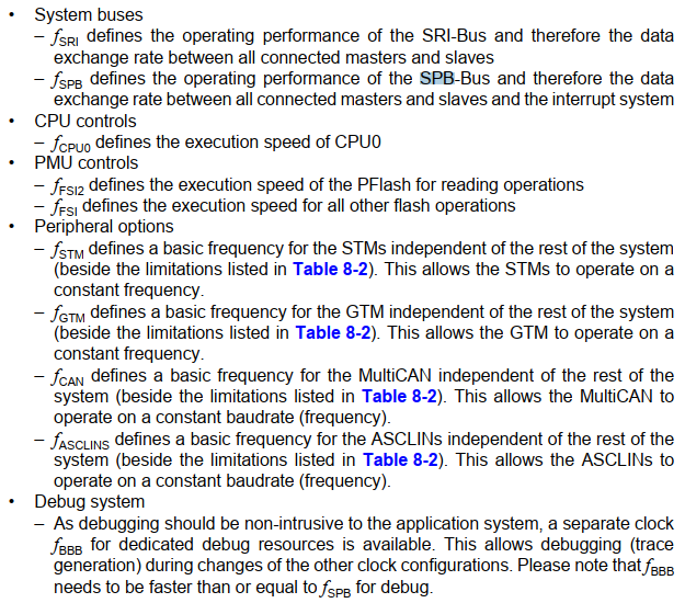
Divide this 200MHz appropriately and distribute it to peripheral devices so that each peripheral device can use the clock.
For example, clocks are shown below.

There is a maximum clock that can be used in the module (peripheral device), so 200MHz should be used carefully.
Eventually, clocks are distributed in the following flow.
20MHz (External OSC) -> 200MHz through PLL -> Connect this to be used by CPU, and divide 200MHz appropriately into clocks that can be used by peripheral devices and distribute them
'Embedded SW > [Infineon] TC275 English Version' 카테고리의 다른 글
| 09. Before development, let’s organize the SW code (TC275, Infineon) (0) | 2023.09.03 |
|---|---|
| 08. Let's design a timer using Infineon TC275 MCU (0) | 2023.08.27 |
| 06. Understanding MCU Clock, Oscillator (Infineon TC275) (0) | 2023.08.26 |
| 05. Digital output settings and LED blinking using TC275 (push-pull, open drain) (0) | 2023.08.26 |
| 04. How to create an MCU TC275 project (Infineon) (0) | 2023.08.26 |


댓글