Today, we will blink the built-in LED of the TC275 board.
This article is one of the articles that serialize the overall contents of development.
So, if you look at the previous article, I think it will be more helpful.
I will link the article below. Read it if you need to.
(Of course, there is no big problem if you just read this article.)
00. Embedded SW development using TC275 (Prologue)
01. What is embedded SW and what is MCU (Micro Control Unit)?
02. How to purchase an embedded development board (TC275, Infineon)
03. How to set up an embedded SW development environment (what is a source code editor, compiler, and debugger environment)
04. How to create an MCU TC275 project (Infineon)
The most important thing in the process of developing an MCU is blinking the LED.
It’s the most basic, yet important.
Let’s turn on LED1 below.

p00.5 is visible.
So let’s take a look at the circuit.

Looking at the circuit diagram, it looks like this:
The pin number p00.5 comes out of the MCU, and it is connected to the LED.

If the MCU side is grounded, the current will flow to the MCU side and the LED will turn on.
When the MCU reaches 3.3V, no current flows and the LED turns off.
Then, let’s try operating the MCU once.
/**********************************************************************************************************************
 * \file Cpu0_Main.c
 * \copyright Copyright (C) Infineon Technologies AG 2019
 *
 * Use of this file is subject to the terms of use agreed between (i) you or the company in which ordinary course of
 * business you are acting and (ii) Infineon Technologies AG or its licensees. If and as long as no such terms of use
 * are agreed, use of this file is subject to following:
 *
 * Boost Software License - Version 1.0 - August 17th, 2003
 *
 * Permission is hereby granted, free of charge, to any person or organization obtaining a copy of the software and
 * accompanying documentation covered by this license (the "Software") to use, reproduce, display, distribute, execute,
 * and transmit the Software, and to prepare derivative works of the Software, and to permit third-parties to whom the
 * Software is furnished to do so, all subject to the following:
 *
 * The copyright notices in the Software and this entire statement, including the above license grant, this restriction
 * and the following disclaimer, must be included in all copies of the Software, in whole or in part, and all
 * derivative works of the Software, unless such copies or derivative works are solely in the form of
 * machine-executable object code generated by a source language processor.
 *
 * THE SOFTWARE IS PROVIDED "AS IS", WITHOUT WARRANTY OF ANY KIND, EXPRESS OR IMPLIED, INCLUDING BUT NOT LIMITED TO THE
 * WARRANTIES OF MERCHANTABILITY, FITNESS FOR A PARTICULAR PURPOSE, TITLE AND NON-INFRINGEMENT. IN NO EVENT SHALL THE
 * COPYRIGHT HOLDERS OR ANYONE DISTRIBUTING THE SOFTWARE BE LIABLE FOR ANY DAMAGES OR OTHER LIABILITY, WHETHER IN
 * CONTRACT, TORT OR OTHERWISE, ARISING FROM, OUT OF OR IN CONNECTION WITH THE SOFTWARE OR THE USE OR OTHER DEALINGS
 * IN THE SOFTWARE.
 *********************************************************************************************************************/
#include "Ifx_Types.h"
#include "IfxCpu.h"
#include "IfxScuWdt.h"

#include "IfxPort.h"
#include "IfxPort_PinMap.h"

IfxCpu_syncEvent g_cpuSyncEvent = 0;

int core0_main(void)
{
    IfxCpu_enableInterrupts();

    /* !!WATCHDOG0 AND SAFETY WATCHDOG ARE DISABLED HERE!!
     * Enable the watchdogs and service them periodically if it is required
     */
    IfxScuWdt_disableCpuWatchdog(IfxScuWdt_getCpuWatchdogPassword());
    IfxScuWdt_disableSafetyWatchdog(IfxScuWdt_getSafetyWatchdogPassword());

    /* Wait for CPU sync event */
    IfxCpu_emitEvent(&g_cpuSyncEvent);
    IfxCpu_waitEvent(&g_cpuSyncEvent, 1);

    /*P00_5    Digital Output*/
    IfxPort_setPinModeOutput(IfxPort_P00_5.port, IfxPort_P00_5.pinIndex, IfxPort_OutputMode_pushPull, IfxPort_OutputIdx_general);
    IfxPort_setPinLow(IfxPort_P00_5.port, IfxPort_P00_5.pinIndex);

    while(1)
    {

    }
    return (1);
}
Please refer to the source code above.
Port 00.5 is set as output, and it is set as push pull.
And, I set this low to ground.
The current will then pass through the LED and turn it on.
Then connect it to the debugger and check it out.

Let’s run it once, and then we’ll stop.
And let’s open the Register once.
Double-click the part circled in red at the bottom.

Now let’s take a look at the ports.
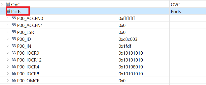
And since we set number 00.5 as output
Let’s take a look at the registers.

It is set to 0x10.
So let’s take a look.
What is the IOCR register?
I set it to 0x10, what does it mean?

IOCR is called Input/Output Control Register.
In other words, it can be called a resetter that sets the pin as input/output.
Then, since I need to set №00.5, I will try to change No. PC5 once.
So how should I set that value?

There are two ways to set the output.
0x10 -> output push-pull
0x18 -> output open-drain
I set it to 0x10.
So what’s the difference between the two?
Let’s take a closer look at the Digital Output settings (Push pull, open drain arrangement).
First, it is an open drain circuit.

Square box means MCU.
What you can do in the MCU is to ground it to ground by pressing the switch.
If the switch is not pressed, you can see that it is just floating.
Therefore, Open Drain method setup requires additional circuit configuration.
Then I will make a circuit like the one below.

If you press the switch on the MCU, the current flows and the LED turns on.
It is mainly used when operating an IC using the power of an external power supply.
Now let’s think about push pull setting.

You can definitely set it to 3.3V or Ground.
At this time, 3.3V uses the VDD power inside the MCU.
At this time, the current is weak because the current is really only enough to operate the switch.
But obviously there is no floating state because you can definitely set it to 3.3V and Ground.
I set it to push-pull to run the LED.
Like this!

So, now that we’ve turned on the LED, let’s move on to blinking the LED.
What’s so important about blinking an LED?
Ten years ago, while reading a lot of embedded-related lyrics, I wondered why the embedded started with LED Blinking.
Because Blinking using GPO is the most basic?
Yes, you’re right.
But the more accurate reason is to generate absolute time using interrupts.
In other words, Frimware SW requires a scheduler.
At this time, what is needed when creating a scheduler is absolute time.
Embedded SW can be divided into Firmware SW and OS SW.
There is a separate OS called RTOS that is put on embedded software. Of course, you can also upload an embedded Linux OS.
In this case, the OS does the scheduling.

However, there are many cases where most microcomputers do not require an OS.
Therefore, software is developed by creating a scheduler directly without loading the OS.
‘What is important when developing Fimware SW?’ If you ask me, I say the two below.
1) Creating a scheduler, securing and analyzing real-time performance of SW
2) Efficient memory-related control (Linker Script file design)
In fact, handling peripherals well is the most basic thing.
Of course, it is also very important to read the MCU reference manual and design the registers of the peripherals well.
However, it is the parts 1) and 2) that cause problems later.
I will slowly explain why 1) and 2) are important.
First of all, I mentioned that the concept of blinking LEDs is needed to create a scheduler among 1) times.
Then let’s think about it. How can I blink an LED?
while(1)
{
   for(i=0;i<10000;i++){};
   LED_ON();
   for(i=0;i<10000;i++){};
   LED_OFF();
}
You can check it with the code above.
After a certain period of time, set the GPO to Gound to turn on the LED, and after a certain period of time, set the GPO to 3.3V to turn off the LED.

If so, now I want to make an electronic watch.
I want to blink the LED inside the electronic clock once per second.
Then, what should be the counter of the for statement?
Let’s assume that we found the value of 10000000 after a lot of trial and error considering the performance of the CPU.
But let’s assume that I created an additional function other than LED ON and OFF.
while(1)
{
   for(i=0;i< 10000000;i++){};
   LED_ON();
   for(i=0;i< 10000000;i++){};
   LED_OFF();

   ADD_Function();
}
In this case we have to find the parameters again.
It looks like the 10000000 at the top should be reduced more because the function runs more at the bottom.
In embedded, securing absolute time is the most basic and important task of embedded software.
The necessity is recognized through LED Blinkning.
Then, in order to confirm the absolute time, let’s learn about the concept of Timer and Interrupt, which are the flower of embedded.


댓글