임베디드 SW 개발에 있어서 가장 중요하다는 부분이 Clock Setting이라고 생각한다.
모든 주변기기의 동작은 Clock을 받아 동작하기 때문에 몇 Hz의 Clock이 주변기기로 들어오는지를
정확히 알아야 한다.
TC237 개발 보드에는 20MHz의 외부 오실레이터가 달려 있다.

이 오실레이터를 기반으로 PLL(Phase Lock Loop)모듈을 통하여 더 높은 Hz로 분주를 한다.
이 PLL 모듈은 아래 System Control Unit 아래 CCU 모듈안에 있다.


위의 그림을 보면 20MHz의 외부 오실레이터를 input으로 받아서 200MHz의 주파수를 만들어 내는 것을 볼수 있다.
TC237 MCU의 최대 주파수는 200MHz 까지기 때문에 최대한으로 분주하였다.
이제 어떻게 분주가 되는지를 알아 보도록 하자!


위의 레지스터설정값을 보고 계산을 해보자
200MHz = 60/(2*3)*20 = 200MHz가 된다.
N = NDIV + 1
P = PDIV + 1
K2 = K2DIV + 1
으로 계산한다.

물론 이러한 Clock 초기화는 ILLD Start Code에서 수행해주고, main 함수로 jump한다.
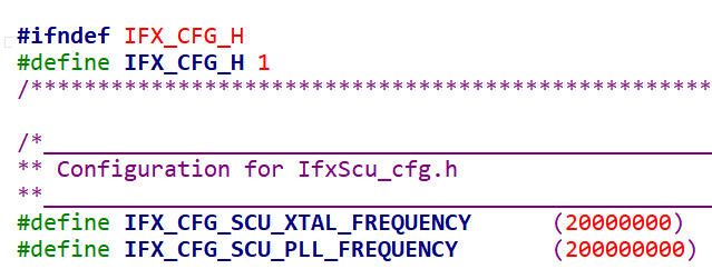
따라서 우리는 Config 설정만 잘 하면 된다.

위의 코드는 외부 오실레이터를 20MHz를 이용하여 200MHZ의 PLL Output을 만들어 달라고 넣는 input 값이다.
코드를 살펴 보면 ILLD Start Code의 마지막 부분에서 Clock 초기화를 시켜준다.
아래는 ILLD Clock 초기화 코드이다.
boolean IfxScuCcu_init(const IfxScuCcu_Config *cfg)
{
    uint8   smuTrapEnable;
    uint16  endinit_pw, endinitSfty_pw;
    boolean status = 0;
    /* Store the crystal frequency */
    IfxScuCcu_xtalFrequency = cfg->xtalFrequency;

    endinit_pw              = IfxScuWdt_getCpuWatchdogPassword();
    endinitSfty_pw          = IfxScuWdt_getSafetyWatchdogPassword();

    {
        /* Disable TRAP for SMU (oscillator watchdog and unlock detection) */
        IfxScuWdt_clearCpuEndinit(endinit_pw);
        smuTrapEnable      = SCU_TRAPDIS.B.SMUT;
        SCU_TRAPDIS.B.SMUT = 1U;
        IfxScuWdt_setCpuEndinit(endinit_pw);
    }

    {
        /* Select fback (fosc-evr) as CCU input clock */
        IfxScuWdt_clearSafetyEndinit(endinitSfty_pw);

        while (SCU_CCUCON0.B.LCK != 0U)
        {
            /*Wait till ccucon0 lock is set */
            /*No "timeout" required, because if it hangs, Safety Endinit will give a trap */
        }

        SCU_CCUCON0.B.CLKSEL = 0; /*Select the EVR as fOSC for the clock distribution */
        SCU_CCUCON0.B.UP     = 1; /*Update the ccucon0 register */

        /* Disconnet PLL (SETFINDIS=1): oscillator clock is disconnected from PLL */
        SCU_PLLCON0.B.SETFINDIS = 1;
        /* Now PLL is in free running mode */

        /* Select Clock Source as PLL input clock */
        while (SCU_CCUCON0.B.LCK != 0U)
        {
            /*Wait till ccucon0 lock is set */
            /*No "timeout" required, because if it hangs, Safety Endinit will give a trap */
        }

        SCU_CCUCON1.B.INSEL = 1; /*Select oscillator OSC0 as clock to PLL */
        SCU_CCUCON1.B.UP    = 1; /*Update the ccucon0 register */

        status             |= IfxScuCcu_isOscillatorStable();

        IfxScuWdt_setSafetyEndinit(endinitSfty_pw);
    }

    if (status == 0)
    {
        /*Start the PLL configuration sequence */
        uint8 pllStepsCount;

        /*Setting up P N and K2 values equate pll to evr osc freq */
        {
            {
                /*Set the K2 divider value for the step corresponding to step count */
                IfxScuWdt_clearSafetyEndinit(endinitSfty_pw);

                while (SCU_PLLSTAT.B.K2RDY == 0U)
                {
                    /*Wait until K2 divider is ready */
                    /*No "timeout" required because Safety Endinit will give a trap */
                }

                SCU_PLLCON1.B.K2DIV = cfg->sysPll.pllInitialStep.k2Initial;

                {
                    /*change P and N divider values */
                    SCU_PLLCON0.B.PDIV = cfg->sysPll.pllInitialStep.pDivider;
                    SCU_PLLCON0.B.NDIV = cfg->sysPll.pllInitialStep.nDivider;

                    /* Disable oscillator disconnect feature
                     * in case of PLL unlock, PLL stays connected to fref */
                    SCU_PLLCON0.B.OSCDISCDIS = 1;
                    //                    workaround for Errata: PLL TC 005
                    SCU_PLLCON0.B.PLLPWD     = 0; // set PLL to power down
                    /* Connect PLL to fREF as oscillator clock is connected to PLL   */
                    SCU_PLLCON0.B.CLRFINDIS  = 1;
                    SCU_PLLCON0.B.PLLPWD     = 1; // set PLL to normal

                    /* Restart PLL lock detection (RESLD = 1) */
                    SCU_PLLCON0.B.RESLD = 1;

                    IfxScuCcu_wait(0.000050F);  /*Wait for 50us */

                    while (SCU_PLLSTAT.B.VCOLOCK == 0U)
                    {
                        /* Wait for PLL lock */
                        /*No "timeout" required, because if it hangs, Safety Endinit will give a trap */
                    }

                    SCU_PLLCON0.B.VCOBYP = 0; /*VCO bypass disabled */

                    while (SCU_CCUCON0.B.LCK != 0U)
                    {
                        /*Wait till ccucon registers can be written with new value */
                        /*No "timeout" required, because if it hangs, Safety Endinit will give a trap */
                    }

                    SCU_CCUCON0.B.CLKSEL = 0x01;

                    /*Configure the clock distribution */
                    while (SCU_CCUCON0.B.LCK != 0U)
                    {
                        /*Wait till ccucon registers can be written with new value */
                        /*No "timeout" required, because if it hangs, Safety Endinit will give a trap */
                    }

                    /*Wait until the initial clock configurations take in to effect for the PLL*/
                    IfxScuCcu_wait(cfg->sysPll.pllInitialStep.waitTime); /*Wait for configured initial time */

                    {                                                    /*Write CCUCON0 configuration */
                        Ifx_SCU_CCUCON0 ccucon0;
                        ccucon0.U        = SCU_CCUCON0.U & ~cfg->clockDistribution.ccucon0.mask;
                        /*update with configured value */
                        ccucon0.U       |= (cfg->clockDistribution.ccucon0.mask & cfg->clockDistribution.ccucon0.value);
                        ccucon0.B.CLKSEL = 0x01;    /*  Select fpll as CCU input clock, even if this was not selected by configuration */
                        ccucon0.B.UP     = 1;
                        SCU_CCUCON0      = ccucon0; /*Set update bit explicitly to make above configurations effective */
                    }

                    while (SCU_CCUCON1.B.LCK != 0U)
                    {
                        /*Wait till ccucon registers can be written with new value */
                        /*No "timeout" required, because if it hangs, Safety Endinit will give a trap */
                    }

                    {
                        /*Write CCUCON1 configuration */
                        Ifx_SCU_CCUCON1 ccucon1;
                        ccucon1.U       = SCU_CCUCON1.U & ~cfg->clockDistribution.ccucon1.mask;
                        /*update with configured value */
                        ccucon1.U      |= (cfg->clockDistribution.ccucon1.mask & cfg->clockDistribution.ccucon1.value);
                        ccucon1.B.INSEL = 1;
                        ccucon1.B.UP    = 1;
                        SCU_CCUCON1     = ccucon1;
                    }

                    while (SCU_CCUCON2.B.LCK != 0U)
                    {
                        /*Wait till ccucon registers can be written with new value */
                        /*No "timeout" required, because if it hangs, Safety Endinit will give a trap */
                    }

                    {
                        /*Write CCUCON2 configuration */
                        Ifx_SCU_CCUCON2 ccucon2;
                        ccucon2.U    = SCU_CCUCON2.U & ~cfg->clockDistribution.ccucon2.mask;
                        /*update with configured value */
                        ccucon2.U   |= (cfg->clockDistribution.ccucon2.mask & cfg->clockDistribution.ccucon2.value);
                        ccucon2.B.UP = 1;
                        SCU_CCUCON2  = ccucon2;
                    }

                    while (SCU_CCUCON5.B.LCK != 0U)
                    {           /*Wait till ccucon registers can be written with new value */
                        /*No "timeout" required, because if it hangs, Safety Endinit will give a trap */
                    }

                    {           /*Write CCUCON5 configuration */
                        Ifx_SCU_CCUCON5 ccucon5;
                        ccucon5.U    = SCU_CCUCON5.U & ~cfg->clockDistribution.ccucon5.mask;
                        /*update with configured value */
                        ccucon5.U   |= (cfg->clockDistribution.ccucon5.mask & cfg->clockDistribution.ccucon5.value);
                        ccucon5.B.UP = 1;
                        SCU_CCUCON5  = ccucon5;
                    }

                    {           /*Write CCUCON6 configuration */
                        Ifx_SCU_CCUCON6 ccucon6;
                        ccucon6.U   = SCU_CCUCON6.U & ~cfg->clockDistribution.ccucon6.mask;
                        /*update with configured value */
                        ccucon6.U  |= (cfg->clockDistribution.ccucon6.mask & cfg->clockDistribution.ccucon6.value);
                        SCU_CCUCON6 = ccucon6;
                    }
                }

                IfxScuWdt_setSafetyEndinit(endinitSfty_pw);
            }
        }

        {           /*Write Flash waitstate configuration */
            Ifx_FLASH_FCON fcon;
            fcon.U = FLASH0_FCON.U & ~cfg->flashFconWaitStateConfig.mask;

            /*update with configured value */
            fcon.U &= ~cfg->flashFconWaitStateConfig.mask;
            fcon.U |= (cfg->flashFconWaitStateConfig.mask & cfg->flashFconWaitStateConfig.value);
            {
                IfxScuWdt_clearCpuEndinit(endinit_pw);
                FLASH0_FCON = fcon;
                IfxScuWdt_setCpuEndinit(endinit_pw);
            }
        }

        /*Start Pll ramp up sequence */
        for (pllStepsCount = 0; pllStepsCount < cfg->sysPll.numOfPllDividerSteps; pllStepsCount++)
        {                       /*iterate through number of pll steps */
            {
                IfxScuWdt_clearSafetyEndinit(endinitSfty_pw);

                /*Configure K2 divider */
                while (SCU_PLLSTAT.B.K2RDY == 0U)
                {
                    /*Wait until K2 divider is ready */
                    /*No "timeout" required, because if it hangs, Safety Endinit will give a trap */
                }

                /*Now set the K2 divider value for the step corresponding to step count */
                SCU_PLLCON1.B.K2DIV = cfg->sysPll.pllDividerStep[pllStepsCount].k2Step;
                IfxScuWdt_setSafetyEndinit(endinitSfty_pw);
            }

            /*call the hook function if configured */
            if (cfg->sysPll.pllDividerStep[pllStepsCount].hookFunction != (IfxScuCcu_PllStepsFunctionHook)0)
            {
                cfg->sysPll.pllDividerStep[pllStepsCount].hookFunction();
            }

            /*Wait for waitCounter corresponding to the pll step */
            IfxScuCcu_wait(cfg->sysPll.pllDividerStep[pllStepsCount].waitTime);
        }
    }

    {                           /* Enable oscillator disconnect feature */
        IfxScuWdt_clearSafetyEndinit(endinitSfty_pw);
        SCU_PLLCON0.B.OSCDISCDIS = 0U;
        IfxScuWdt_setSafetyEndinit(endinitSfty_pw);
    }
    {
        /* Enable VCO unlock Trap if it was disabled before */
        IfxScuWdt_clearCpuEndinit(endinit_pw);
        SCU_TRAPCLR.B.SMUT = 1U;
        SCU_TRAPDIS.B.SMUT = smuTrapEnable;
        IfxScuWdt_setCpuEndinit(endinit_pw);
    }
    return status;
}
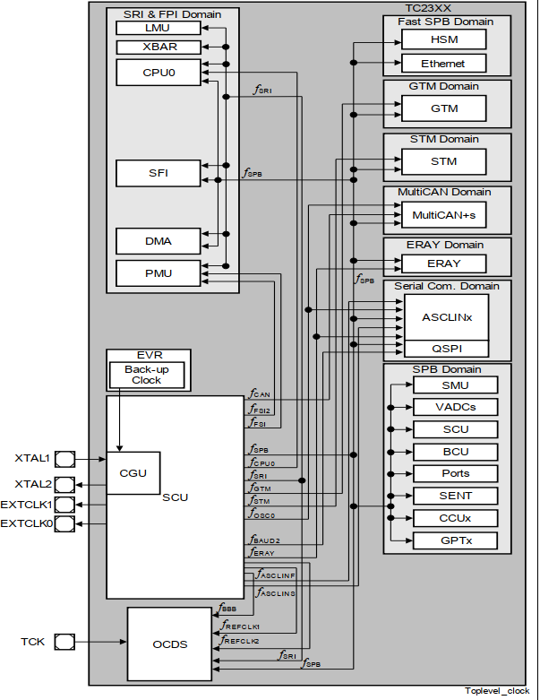
그러면 이렇게 최종 분주된 값을 CCU 모듈에서 잘 조절해서 주변기기들로 배분시켜 준다.

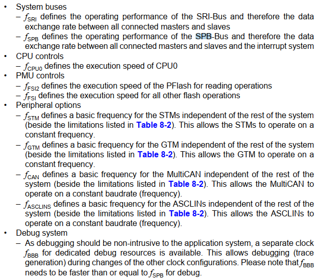
위의 Clock들의 설명은 아래를 참고한다.

마지막으로 이러한 Clock이 ILLD를 통하여 어떻게 세팅이 되었는지를 정리하고 마무리 하려고 한다.
fsource = 200MHz
fSRI = 200MHz
fSPB = 100MHz
fCPU0 = 200MHz
fFSI = 100MHz
fSTM = 100MHz
fGTM = 100MHz
fCAN = 100MHz
이것은 각 Clock이 사용할수 있는 최대 Clock들이고 이것을 ILLD SW가 알아서 맞추어 주었다.
문론 직접 설계해도 괜찮다.
NXP 계열 MCU는 보통 직접설계한다.
그런데, 인피니어은 MCAL, ILLLD등의 Stack을 이용하여 Clock 세팅을 하는것이 더 안전하다.
따라서 잘 쓸수 있는것은 가져다가 잘 쓰면 된다 ㅎㅎ
'Embedded SW > [Infineon] Embedded SW Project' 카테고리의 다른 글
| [Infineon] 15. Aurix (TC23x)를 이용한 DC 모터 동작 수행 1 (L298N, FIT0450) (0) | 2021.06.12 |
|---|---|
| [Infineon] 14. Aurix (TC23x)를 이용한 DC 모터 동작 수행 1 (L298N, FIT0450) (0) | 2021.05.28 |
| [Infineon] 12. Aurix (TC23x) GTM TOM을 이용한 PWM 출력 (3) | 2021.05.27 |
| [Infineon] 11. Aurix (TC23x) TFT를 이용한 디버깅 환경 구축 (0) | 2021.05.25 |
| [Infineon] 06. Aurix (TC23x) 인터럽트 Interrupt 이해하기 (2) (6) | 2021.05.19 |


댓글